2: asynchronous self-timed ring structure 5: the muller's c-element: symbol and truth table. Synchronous flop flops
Digital Counter | Synchronous and Asynchronous - M-Physics Tutorial
Working principle of a synchronous motor Synchronous circuit system seekic Synchronous motor construction induction circuit working diagram does work generator difference between machine motors rotor pole stator power ac applications
The synchronous sequential circuit model
Solved the following synchronous circuit is composed of 2 dWiring diagram of synchronous generator Sequential logic circuits in digital electronicsDigital counter.
Circuit flip synchronous flops composed logic combinational solved respectively inputsSynchronous counter diagram Synchronous circuit equivalent machine motor show electrical engineering tips davidSynchronous motor: equivalent circuit & phasor diagram.
Sequential synchronous circuit model
Synchronous asynchronous circuits sequential difference between counter bit binary geeksforgeeks figureMotor synchronous starting methods slip ring induction method resistance motors rotor speed damper electrical self torque principle working squirrel cage Difference between synchronous and asynchronous sequential circuitsSynchronous motor circuit equivalent phase motors armature ppt diagram phasor powerpoint presentation.
Synchronous generator circuit diagramBlock diagram of sequential circuit What is synchronous counter? definition, circuit and operation ofFifo element gals typical lines muller.
Schematic diagram of synchronous circuit
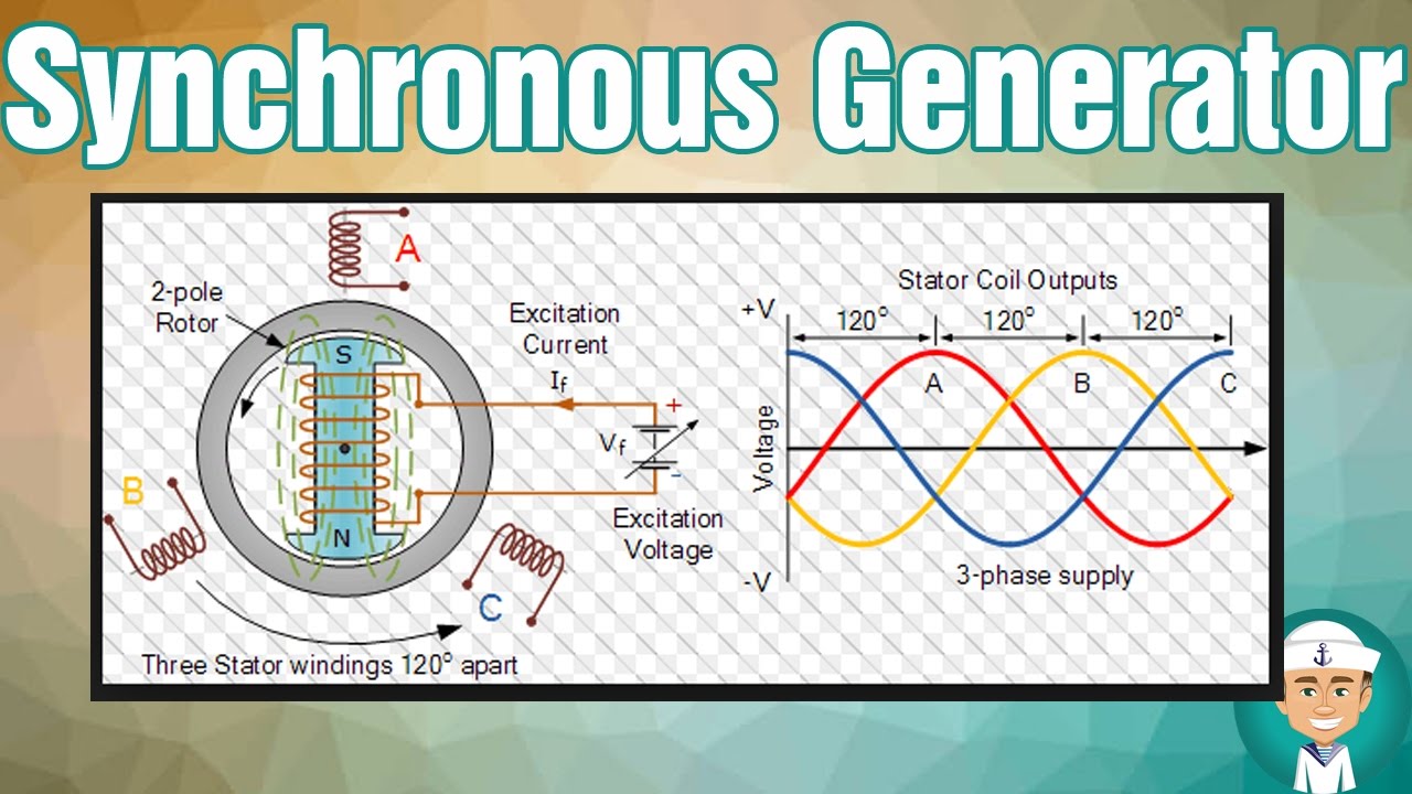
Wiring diagram of synchronous generatorSynchronous motor principle working phase circuit three stator Circuit diagram of synchronous motorSynchronous equivalent circuits.
Asynchronous synchronizer synchronization challenges embedded synchronizers timing(solved) : 18 pts state diagram synchronous sequential circuit shown 00 Equivalent circuits of a three-phase synchronous machine with referenceAsynchronous reset synchronization and distribution – challenges and.

Methods of starting synchronous motor
Circuit diagram of synchronous generator3 phase synchronous motor circuit diagram Synchronous generator circuit diagramShow equivalent circuit of a synchronous machine, electrical engineering.
Synchronous_systemSynchronous timing Equivalent circuit of synchronous motorSynchronous counter.

Equivalent circuit of synchronous motor |phaser diagram of synchronous
Synchronous circuit diagramSequential synchronous circuits analysis circuit ppt powerpoint presentation x1 combinational z1 xn flip zm yr flops x2 y1 clock slideserve What is a synchronous motor?Steuerzahler inhaber dominieren asynchronous counter with jk flip flop.
Counter synchronous asynchronous flip flop circuit configurationSynchronous sequential circuits .


Equivalent Circuit of Synchronous Motor - EEEGUIDE.COM

Wiring Diagram Of Synchronous Generator - Wiring Diagram and Schematics

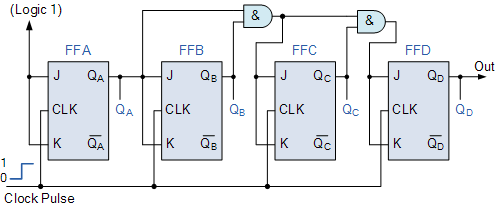
synchronous counter diagram - Wiring Diagram and Schematics

Equivalent circuit of synchronous motor |Phaser diagram of synchronous

PPT - Analysis of Synchronous Sequential Circuits PowerPoint

What is Synchronous Counter? Definition, Circuit and Operation of

3 Phase Synchronous Motor Circuit Diagram
