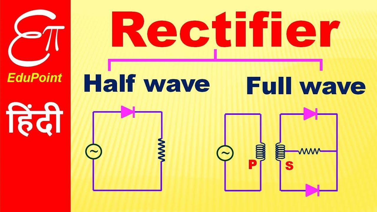
Full wave bridge rectifier – circuit diagram and working principle 4df Rectifier wave half full circuit diode voltage diagram output waveform ac figure input positive cycle dc principle working converts Rectifier circuit diagram
Rectifier Circuit Diagram | Half Wave, Full Wave, Bridge - ETechnoG
Single phase half wave rectifier- circuit diagram,theory & applications Rectifier wave half With neat circuit diagram and waveforms explain the operation of full
Describe the half wave rectifier using diode
Wave rectifier half full difference between circuit figure comparisonComparison of half wave rectifiers and full wave rectifiers Half rectifier circuit diagramRectifier circuit diagram.
Half wave rectifier(explanation)Half and full wave rectifier working principle What is half wave and full wave rectifier operation amp circuit diagramDifference between half wave and full wave rectifier (with comparison.

10+ half wave rectifier diagram
Half voltage full high wave rectifier electrical engineering rectifiers transformer circuits conducting secondary maximum cycle maxRectifier wave full half diode byjus diodes physics characteristics Half wave rectifier full difference between diode definitionDiode as a rectifier.
Rectifier voltage circuits circuitdigest debashis☑ filter capacitor formula for half wave rectifier Half wave and full wave rectifierDescribe the half wave rectifier using a diode.

Half wave rectifier basics, circuit, working applications, 50% off
Rectifier waveformHalf and full wave rectifier circuits Rectifier transformer tapped output input waveformRectifier rectifiers circuits.
Half wave and full wave precision rectifier circuit using op-ampFull wave rectifier: working principle, diagram, and formula Rectifiers wave half full comparison circuit diagram waves engineering engineeringtutorial visitHalf wave & full wave rectifier: working principle, circuit diagram.

Half wave rectifier circuit simulation download scientific diagram
[diagram] circuit diagram rectifierDifference between half wave and full wave rectifier (with comparison Rectifier circuit rectifiersRectifier operation capacitor diode circuits load rl circuitstoday 2009.
High voltage facts for undergraduate and postgraduate students ofRectifier half output voltage principle .

Half Wave Rectifier Basics, Circuit, Working Applications, 50% OFF

Half and Full Wave Rectifier Circuits | Ripple Voltage

Difference between Half Wave and Full Wave Rectifier (with Comparison

Half Wave Rectifier Circuit Simulation Download Scientific Diagram - Riset

Describe the Half Wave Rectifier Using Diode

Rectifier Circuit Diagram | Half Wave, Full Wave, Bridge - ETechnoG

High voltage facts for undergraduate and postgraduate students of
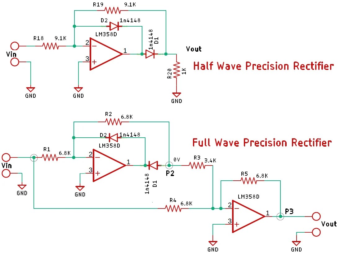
Half Wave and Full Wave Precision Rectifier Circuit using Op-Amp
